
Wanhua SIPs Wall Panel
A structural insulated panel for load-bearing walls
A rigid polyurethane foam core bonded between oriented strand board on both faces. The two OSB skins carry the structural load and the PU core provides the shear connection between them, so the panel acts as one composite wall section — with better thermal and acoustic performance than an equivalent timber or steel stud wall.
Drag to rotate
Panel thicknesses
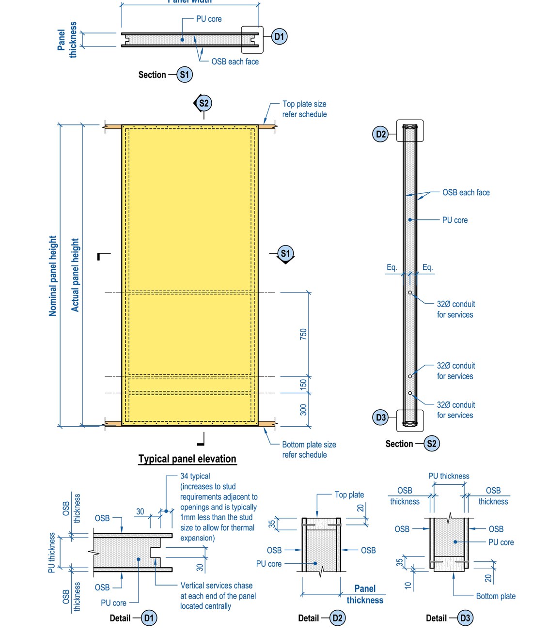
88mm, 94mm, 114mm
Wind rating
Non-cyclonic regions, up to N6
Acoustic rating
Rw 27dB
114mm panel. Intertek Testing Services Shenzhen Ltd.
Thermal resistance (88mm panel)
R 3.30 / 3.15 / 2.91 m²K/W at 15°C / 23°C / 30°C
Intertek Testing Services Shenzhen Ltd.
Thermal resistance (94mm panel)
R 3.34 / 3.20 / 2.95 m²K/W at 15°C / 23°C / 30°C
Intertek Testing Services Shenzhen Ltd.
Panel schedule
Three thicknesses
| Panel | OSB each face | PU core | Plates | Panel weight |
|---|---|---|---|---|
| 114mm | 12mm | 90mm | Top 35×90 · Bottom 45×90 | 28.6 – 71.7 kg |
| 94mm | 12mm | 70mm | Top 35×70 · Bottom 45×70 | 27.3 – 68.4 kg |
| 88mm | 9mm | 70mm | Top 35×70 · Bottom 45×70 | 21.6 – 54.2 kg |
- Standard widths 610mm and 1,220mm
- Nominal heights 2,400 / 2,700 / 3,000mm (actual height 10mm less)
- 18 standard panel sizes in total
- Rated for non-cyclonic wind regions up to and including N6
Materials & assessment
Oriented strand board
OSB/3 grade or higher, to European Standard EN 300:2006 and Chinese Standard CH-LT/T 1580-2010
Rigid polyurethane core
Rigid PU insulation to Chinese National Standard GB 50404-2017
On site
Installation
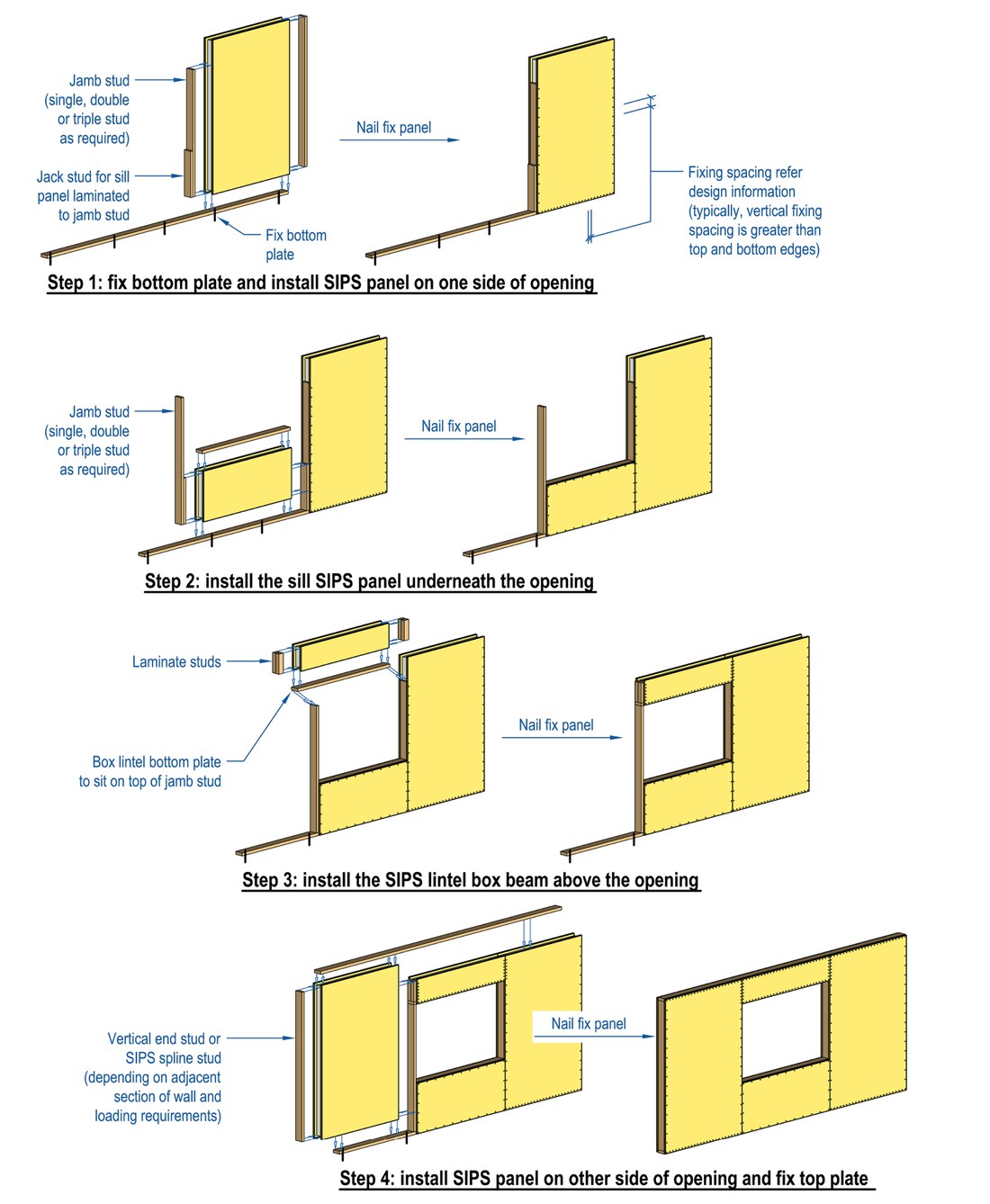
- 1 Clean the slab or sub-structure and mark out the bottom plate locations
- 2 Provide a damp proof membrane between bottom plate and concrete slab
- 3 Fix bottom plates as per the structural drawings
- 4 Erect the panels and provide temporary bracing until the floor or roof diaphragm is built
- 5 Fix panels to the bottom plate, then fix adjacent panels together
- 6 Fix the top plate to the panels
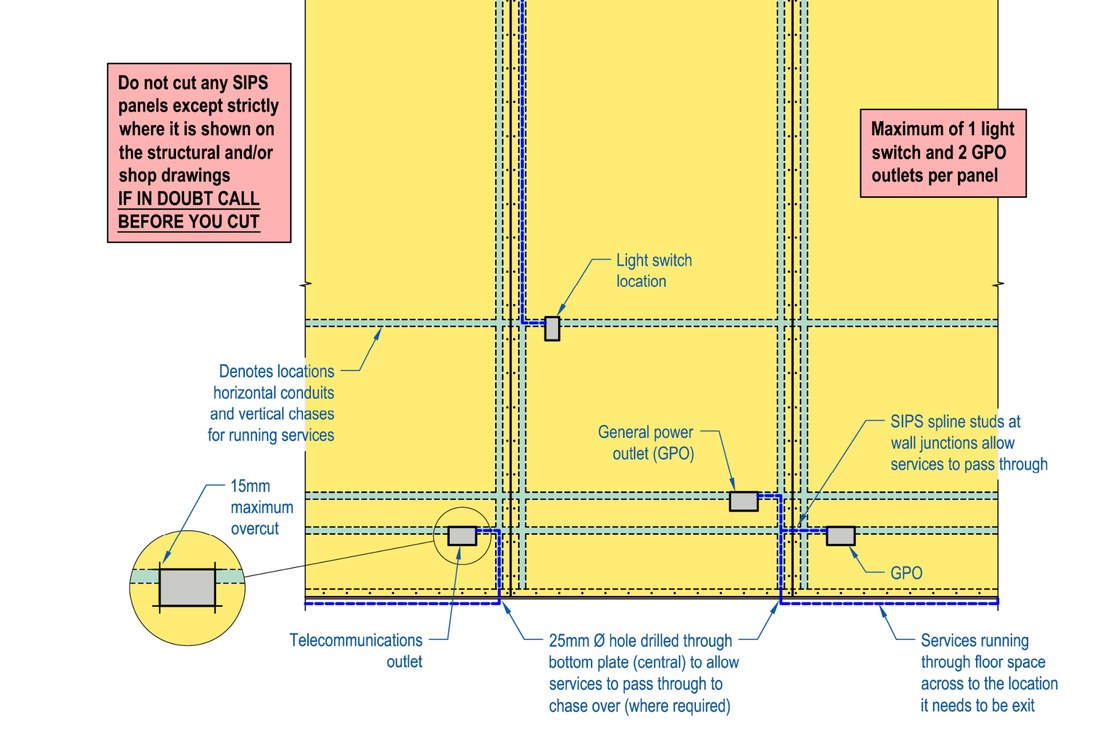
Panels must not be cut or penetrated anywhere other than as shown on the structural and shop drawings.
Services
Cast-in, not cut in
- Horizontal conduits cast in at 300, 450 and 1,200mm from the bottom of the panel
- A 30×30mm vertical services chase at each end of every panel
- Maximum of one light switch and two GPO or telecommunication outlets per panel
- Maximum of one 130mm diameter straight-through penetration per panel for wastewater
Certification
- CodeMark Certified — Certificate CM20260 Certified
CodeMark is a voluntary third-party building product certification scheme that facilitates compliance with Volumes One and Two of the National Construction Code (Building Code of Australia). This certification covers use in Class 1 buildings where no fire rating is required.
- GECA Testing in progress
Good Environmental Choice Australia assessment is underway.